

I have always enjoyed the simple yet sophisticated world of logo design. The logo is a right-brained idea in a left-brained form. Some ideas come to mind quickly, without any effort, as if there could be no other choiceyet others elude us. The logo gives insight into what a company is all about and captures what people should know about the brand.
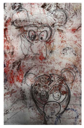
I originally designed the Crack Monkey logo for a class. I wanted to use parts of the same idea in another class, so I used the logo to represent a fictitious T-shirt company. Later on in life, I actually opened my own T-shirt business under this name (Figure 1).
In this tutorial, I show you the steps that went into creating the Crack Monkey logo, and I provide some tips for creating good logos.

Figure 1: Logo for T-shirt design business
Brainstorming for ideas
So how do you come up with great ideas for a logo? There are many ways to brainstorm. You can view logos made by other artists, browse
through logo books, or look online. One of my favorite books for logo ideas is Idea Index: Graphic Effects and Typographic Treatments by Jim Krause (Cincinnati: F+W Publications, 2000). For a good online source, you can visit the Logo Lounge (www.logolounge.com). These and other sources can provide many wonderful ideas to inspire you.
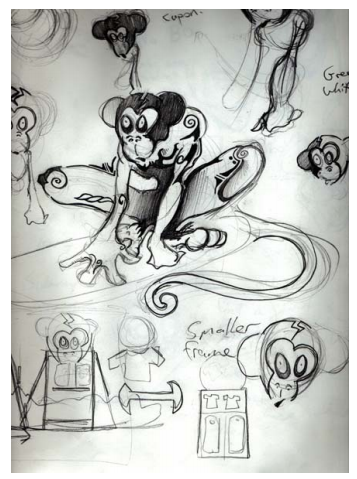
You could also browse through your old sketches (Figure 2). I suggest carrying a sketchbook with you at all times. Draw as much as you can, even if your drawings are nonsensical. Draw everything, and keep your sketchbooks. Browsing through them later can help spark your creativity.
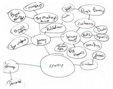
Another brainstorming strategy is to make a mind map in the form of a bubble chart. Using bubble charts is a good way to start thinking about what you want to say about your company. Most people who chuckle at the Crack Monkey logo eventually ask the question, “What do monkeys have to do with buying T-shirts?” My answer is, “Everything.” I felt that a T-shirt company should be edgy yet bizarre, with a twist of crazy. How did I end up with a monkey? I started with a bubble chart.
A bubble chart begins with a central idea that is placed inside a bubble. Extending from this bubble are smaller bubbles, which contain related ideas (Figure 3). After you create a bubble chart, try combining some ideas from the outermost bubbles. Choose two unrelated ideas, and place them side by side. How do those two ideas together sound to you? What do they bring to mind? You can even use those ideas to start new bubble charts that have nothing to do with the first one. If you’re still having trouble coming up with ideas, try learning all you can about the words used on the outside of the bubble chart, and then begin drawing the shapes that come to mind. This process may not spark any ideas at first, but give it time.
A brilliant instructor I had for an illustration class used to tell us, “Make sure to draw at least 50 to 100 thumbnails before you start.” Although I believe that 100 thumbnails is excessive, I understand the importance of brainstorming. Don’t just settle for your first design — experiment, as I did for the Crack Monkey design (Figure 4). If you feel strongly about a particular idea, follow your instincts, and don’t be afraid to make bold statements in your art.
When you have some sketches that you like, choose the one that you want to use as a reference. In this case, I’ll use one of my Crack 4 | CorelDRAW Graphics Suite X5Monkey sketches (Figure 5). You can create a similar sketch and then follow along. Set the resolution of your scanner to 200–300 dpi (dots per inch), and scan the sketch in black and white for easier tracing.
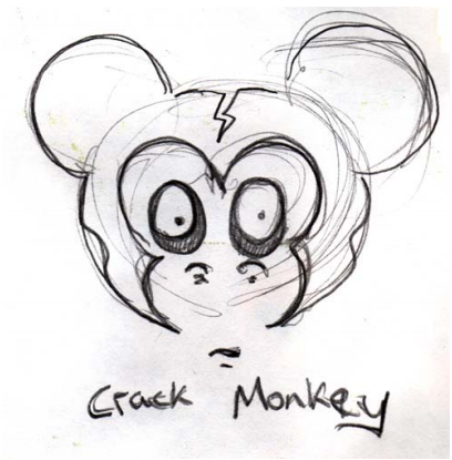
Figure 5: Rough sketch for reference
Working with nodes
When you begin to create your logo, you will draw curves and reshape them by using nodes, so let’s begin by learning a little about nodes.
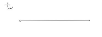
In the toolbox, click the Bézier tool, and click on the page twice, from left to right, to create a line. The line has two nodes, one at each end (Figure 6).
Setting up the document
Start a new CorelDRAW document by clicking File > New. In the Create a new document dialog box, make sure that the Size list box is set to Letter.
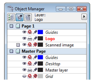
If the Object manager docker is not displayed, click Window > Dockers > Object manager. In the Object manager docker, click the New layer button to create a new layer. Rename the new layer Scanned image, and drag it below Layer 1. Then, rename Layer 1 to Logo. With the Scanned image layer selected, import your sketch.
It’s a good idea to change the color of the black-and-white sketch — a trick that can help you later on when you trace the sketch. In the days before computers, artists would use cyan for sketching, because cyan is not reproduced when the drawing is copied or scanned. Drafters would draw the image in blue and then ink over the blue with black-ink pens of varying line weights. In a similar process, I change the color of my sketch to blue. When I trace with black on top of the blue, I can easily see which parts of the image have been traced. If you import a black-and-white bitmap into CorelDRAW, you can change the white portions by changing the fill color, and you can change the black portions by changing the outline color.
Finally, in the Object manager docker, click the printer and pencil icons next to the Scanned image layer. Clicking the printer icon turns off the printing of that layer, and clicking the pencil icon locks the layer and makes it uneditable (Figure 9). Select the Logo layer. You are now ready to begin!
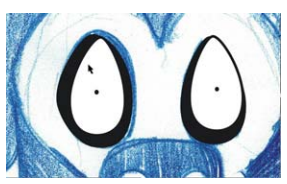
Begin drawing the eyes of the Crack Monkey by drawing an ellipse with the Ellipse tool. Use the underlying sketch as a reference, and draw the ellipse around the eye. Don’t worry about drawing perfectly, because you can edit the ellipse later. Use the Pick tool to position the ellipse (Figure 10).
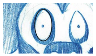
Figure 10: Creating an ellipse over the blue sketch
To modify the ellipse with more precision, you must convert it to curves. Right click the ellipse, and choose Convert to curves. Now the ellipse has four nodes: one at the top, one at the bottom, and one on each side. Double-click the ellipse to activate the Shape tool. Drag to create a selection box around the two side nodes (Figure 11).
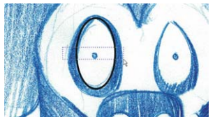
Drag the nodes down to reshape the eye. When you are satisfied with the shape, click outside the nodes to deselect them. Then, select the top node of the ellipse, right-click the node, and make sure that the node is set to Symmetrical. With the top node selected, drag the control handles toward each other to narrow the top of the eye.
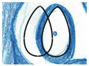
Next, you will create a duplicate of the eye. With the Pick tool, drag the eye to the left. Before releasing the mouse button, right-click once to make a copy of the eye (Figure 12).
The duplicate of the eye is on the topmost layer, but it must be moved to the layer below. You can easily see which object is on top by temporarily applying a different color to each object (Figure 13).
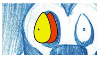
In the Object manager docker, drag the duplicate object below the original one in the stacking order. Then, resize the duplicate, and reshape it to create the black outer ring around the eye. Next, create the tiny iris of the eye by making a perfect circle with the Ellipse tool while holding down Ctrl.
To create the second eye, drag and duplicate the completed right eye (on our left), and mirror the duplicated eye by clicking the Mirror horizontally button on the property bar. Reshape the duplicated eye as needed (Figure 14).
Creating the nose and mouth
Now that you are more comfortable with editing nodes, you can create the nose of the Crack Monkey by using the Bézier tool. Although you can use the Freehand tool to draw the curves, the Bézier tool creates fewer nodes, which is better for creating simple shapes.
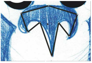
In the toolbox, click the Bézier tool. Using the sketch as a reference, click to place nodes along the shape of the nostrils. Do not be alarmed if the curve you create does not exactly follow the curve in the sketch (Figure 15).
With the nodes in place, you can reshape the curves. Make sure that the nose is selected. Using the Shape tool, drag a selection box around all the nodes. Right-click any of the nodes, and choose To curve. This option Logo Design | 7changes all selected nodes to cusp nodes. Use cusp nodes to create the three sharp corners at the bottom of the nose, and use smooth nodes to create the rest of the curves (Figure 16).
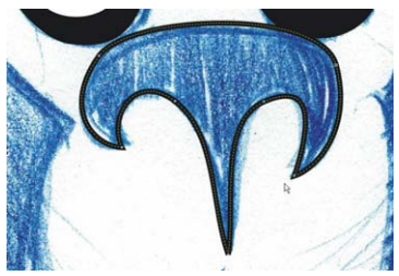
Now that the nose is finished, try to create the mouth and the arch above the lips on your own. When you’re done, click the eye icon next to the Scanned image layer in the Object manager docker to hide the blue sketch (Figure 17).

Figure 17: View of drawing with the sketch hidden
Creating the head and ears
You will create the head and ears without using the sketch as a reference. First, create a new layer, and name it Head. In the Object manager docker, click the eye icon next to the Logo layer to hide it, and make sure that the Head layer is selected.
Using the Ellipse tool, draw an ellipse, and reshape it into an oval for the head (Figure 18). Duplicate the oval, scale the duplicated oval to make it smaller, and move the duplicated oval to the side of the original oval to create the monkey’s right ear (on our left). Then, drag the right node to reshape the curve of the ear (Figure 19).
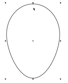
Figure 18: Ellipse for the head
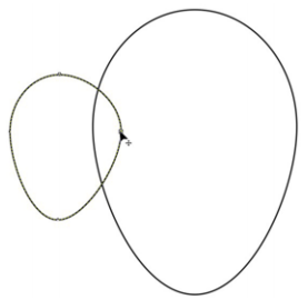
Next, duplicate the ear by dragging it with the Pick tool and right-clicking. This time, hold down the Shift key while dragging to constrain the movement to the horizontal axis.
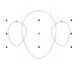
Then, mirror the duplicate, as done earlier with the eyes, to create the second ear.You can use guidelines to make sure that the second ear is the same distance from the center of the head as the first ear. First, make sure that the rulers are displayed, or click View > Rulers to display them. Drag two guidelines from the vertical ruler: one along the inner edge of the monkey’s right ear (on our left), and the other along the right edge of the head (on our left). With one guideline selected, click the other guideline while holding the Shift key, so that both guidelines are selected (Figure 20). If you preserve the distance between the two guidelines, you can use them to align the right and left ears symmetrically, in which case, no measurements are needed! Drag both guidelines to the right, and right-click to duplicate them. Position the duplicates so that the right guideline is aligned with the edge of the head. Click View > Snap to guidelines, and drag the monkey’s left ear so that its inner edge snaps to the left guideline. While dragging the ear, hold down Ctrl to constrain the movement to the horizontal axis (Figure 21).
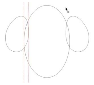
Figure 20: Selecting both guidelines
For Part 2 of this article, click here.
Was this article helpful?
Tell us how we can improve it.